
A current sensor for ECM motors has to tell the motor's standby current from its running current. An electronically commutated motor (ECM) keeps its drive electronics powered whenever line voltage is present, so it draws a small current at rest and only a little more at low speed. A standard current switch often can't resolve that gap, which can leave a building automation system (BAS) with the wrong status point: a running motor reported as off, for example, or an off motor reported as running.
This guide from Functional Devices, Inc. will discuss how to determine which current sensor best fits your specific needs.

Why a Standard Current Switch May Misread an ECM
A current switch closes its contact when the current through the conductor crosses a set threshold. On a standard induction motor, this is straightforward: off is zero amps, running is several amps, and the threshold sits well between them. An ECM removes that margin. Its drive electronics draw a small standby current before the motor turns, and at low commanded speed the running current can be only slightly higher.
A switch with a minimum trip point above the running current never registers the motor, a switch with a trip point below the standby current never releases, and both produce a false reading at the BAS. The sensor that works correctly has two properties: a trip point low enough to set between the standby and running currents, and hysteresis tight enough that the contact holds steady near the setpoint.
Current Switch or Current Transducer: Which Output You Need
What device you need depends on what the BAS has to know. Both types are built around a current transformer (CT): the CT senses the field around the conductor, and the switch or transducer is the finished device that turns that signal into an output the controller reads.
- A current switch outputs an on/off contact closure. It reports whether the load is running and wires to a binary input, for fan proving, pump status, and most ECM run verification.
- A current transducer outputs an analog signal proportional to the current (commonly 4–20 mA, 0–5 V, or 0–10 V). It reports how much the load is drawing and wires to an analog input, for load trending, energy estimation, or fault detection from a changing profile.
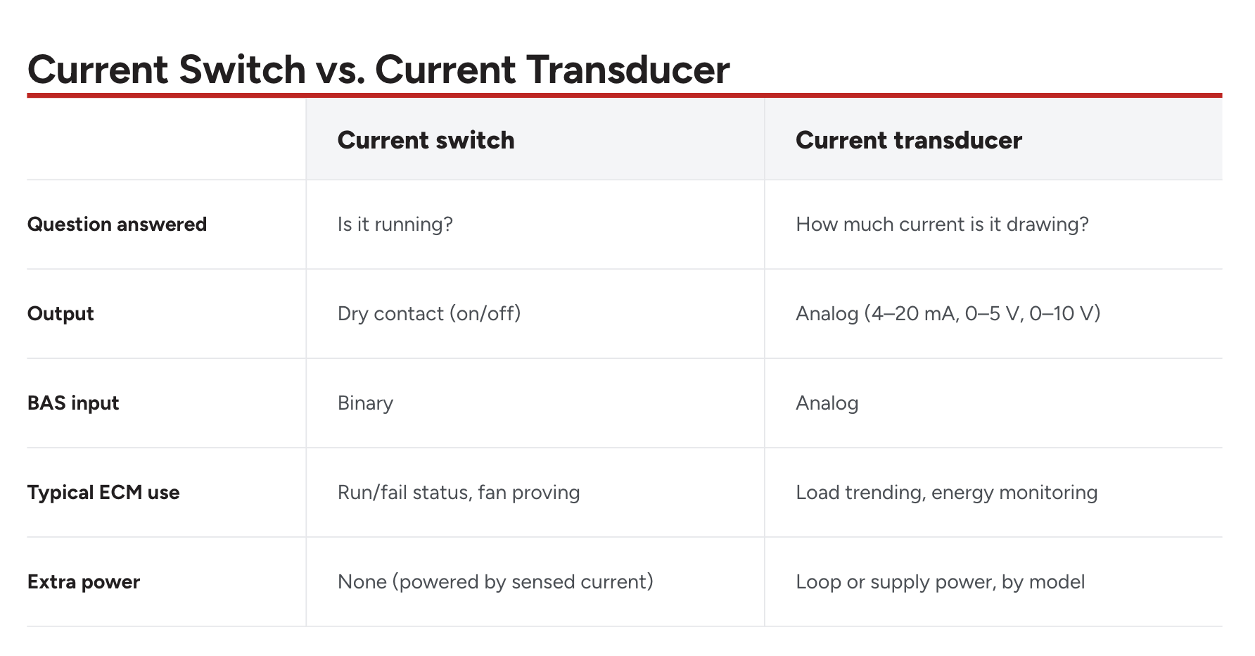
For run status on an ECM or a fan wall, a current switch is sufficient. Use a transducer when you need the current value rather than the on/off state.
What to Look For in a Current Sensor for ECM Loads
Four specifications determine whether a current sensor reads an ECM or fan-wall load correctly.
- Trip point. Use an adjustable model with a trip point that reaches well below 1 A, and set it between the standby and running currents. A fixed-threshold switch can't be tuned to a specific motor.
- Hysteresis. This is the gap between the current that closes the contact and the current that reopens it. A tight gap lets the threshold sit between two close current levels without chattering; a wide gap spans both states and produces false status.
- Core type. A split-core sensor opens to clamp around an existing conductor without disconnecting it, which suits retrofits. A solid-core sensor threads onto the conductor during wiring and is common on new work. Both sense the same way.
- Output type. Match the contact rating and signal type to the BAS point. A switch's solid-state contact goes to a binary input; a transducer's analog signal goes to an analog input.
Sizing Current Sensors for Fan Walls and Fan Arrays
A fan wall uses an array of small ECM-driven fans in place of one large fan. Each fan draws a low current, and the array can be monitored at one fan, a group, or the supply feeding the array.
A single switch on the array feed proves the wall is energized but won't show that one fan has failed. For fan-level fault detection, sense each fan or branch with a trip point low enough to register one small motor rather than the combined load, sized to the smallest motor the status point has to detect.

Functional Devices Current Sensors for ECM Applications
Functional Devices manufactures current switches, current transducers, and combination relay/sensor devices for BAS and commercial building applications. Several models apply to the loads above.
- For ECM run verification, the RIBXGTA-ECM is a split-core current switch with an adjustable trip point as low as 0.25 A and a second LED that indicates load current detected.
- For a solid-core option with a lower trip point, the RIBXKNUTA adjusts down to 0.20 A.
- For adjustable status on larger motors, the split-core RIBXGTA covers 0.75–150 A; the self-calibrating RIBXG-series (-SCAL) models set their own threshold on first run. (Note: For standard induction motors, the self-calibrating RIBXG-series (-SCAL) models set their own threshold on first run, but variable-speed ECMs require the manual tuning of the RIBXGTA-ECM.)
- For an analog current reading rather than status, the RIBXG420 series provides split-core, loop-powered 4–20 mA transducers in 20, 50, and 100 A ranges.
A split-core model clamps onto an existing conductor without disconnecting it, which helps on a retrofit. Functional Devices also makes the relays and power supplies used in the same panel.
Frequently Asked Questions
What current sensor works with ECM motors?
A current switch with a low, adjustable trip point and tight hysteresis, set between the motor's standby and running currents. The RIBXGTA-ECM adjusts down to 0.25 A for this.
Can a standard current switch detect an ECM?
Often not. A higher minimum trip point can miss a low-speed ECM, and a wide hysteresis band can read standby draw as running. A low setpoint with tight hysteresis avoids both.
What is the difference between a current switch and a current transducer?
A current switch outputs an on/off contact closure that reports whether the load is running. A current transducer outputs an analog signal proportional to the current, indicating how much the load is drawing.
Should I use a split-core or solid-core current sensor?
Split-core for retrofits: it clamps around an existing wire without disconnecting it. Solid-core for new installations, where the conductor threads through during wiring.
How do I monitor a fan wall with multiple ECM fans?
A switch on the array feed proves the wall is running. For single-fan fault detection, sense each fan or branch with a trip point low enough to register one small motor.

Source a Current Sensor for ECM Applications
To source a current sensor for an ECM or fan-wall application, contact Functional Devices at 800-888-5538, or find an authorized distributor in your region.