When a complex system finally comes together after months of planning and installation, it can be frustrating to find that something isn’t working as expected. Troubleshooting large systems with multiple devices requires patience, a methodical approach, and a solid understanding of each component—especially when RIB® relays are involved. Since RIB® relays often serve as the critical link between a controller or sensor and a load, confirming their correct operation is an essential step in diagnosing system issues.
The good news? Most RIB® relays can be tested quickly and easily with a few basic tools. This guide will walk you through straightforward troubleshooting steps to help you verify whether your RIB® relay is working as designed, saving you time, effort, and unnecessary frustration.
How to Troubleshoot an RIB® Relay
With just a multimeter and a suitable voltage source, you can perform simple yet effective tests to confirm whether your RIB® relay is functioning correctly. By following these troubleshooting steps—checking contact states, verifying coil operation, and understanding how to handle models with a Hand/Off/Auto switch—you’ll gain confidence in diagnosing relay-related issues within your system. And if your tests show the relay is performing as intended, you’ll know it’s time to look elsewhere for the problem. As always, if you need further assistance, our Technical Support team is ready to help you troubleshoot and keep your system running smoothly.
Answers at a Glance
Q: What should I know about RIB® relays before I get started?
A: RIB® relays have a coil (control) side and a contact (load) side, which correspond to the left and right sides of the data sheet diagram. Understanding both is essential for troubleshooting since you need to verify the operation of each side separately.
Q: What basic tools do I need to troubleshoot a RIB® relay?
A: You’ll need a multimeter (for resistance and voltage readings) and a voltage source that matches the relay’s coil voltage and current requirements (as specified on the product datasheet).
Q: What if my RIB® relay passes all the troubleshooting checks?
A: If your relay meets all the contact state and coil operation checks, it’s functioning correctly. You may need to troubleshoot other parts of your system.
Q: Where can I get more help with troubleshooting?
A: The Functional Devices Technical Support team is always available to help with additional troubleshooting questions or concerns.
Troubleshooting the RIBU1C Relay
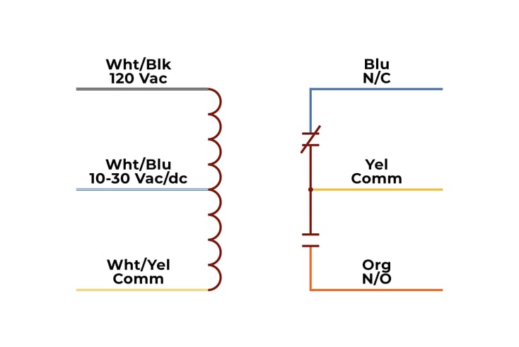
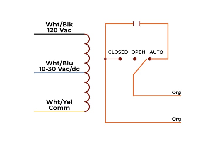
Our relays can be thought of as having two sides, the coil (or control) side, and the contact (or load) side. These are represented on the left and right side of our data sheet diagrams respectively (see Figures 1 and 2 below). For the purposes of this blog, I will be discussing how to troubleshoot the RIBU1C, but the same principles can be applied to most of our relay products. To begin troubleshooting your RIB, you will need a multimeter (for resistance and voltage measurements) and a voltage source compatible with the coil voltage requirements. Make sure the voltage source can supply enough current at the rated voltage to energize the relay. The current requirement can be found on the product data sheet in the "Coil Current" section.
Troubleshooting Steps:
These are general steps that will cover most of our Pilot and Power Series relays. When applying voltage to the input of any device, verify the product is rated to accept that voltage.

Verify normal contact states
- Remove all wire connections to the RIB. This will eliminate external variables and leave only the relay as shown in Figure 1.
- Set the multimeter to read resistance and connect the probes to the Blue and Yellow wires, which is the Normally Closed (N/C) contact. The meter should read a very low resistance (<1„¦).
- Next, connect the probes to the Orange and Yellow wires, which is the Normally Open (N/O) contact. The meter should read near infinite resistance (typically displaying "0L").
Verify coil operation
- Apply 120 Vac to the Wht/Blk and Wht/Yel wires. When doing so, listen for a "click" sound (some models are louder than others). This sound is the relay state changing, and it can be heard when voltage is applied and removed.
- While voltage is applied to the coil input, the red LED on the unit will be ON.
- With voltage still applied, measure the resistance of the contacts again. They should be the opposite of what they were before. The meter should read <1„¦ between the Orange and Yellow wires (N/O contact) and infinite resistance (0L) between the Blue and Yellow wires (N/C contact).
- Next, remove the 120 V source and connect a 10-30 Vac/dc source to the Wht/Blu and Wht/Yel wires.
- The LED on the unit should turn ON and the same "click" should be heard.
- Again, measure the contact resistance and verify there is <1„¦ between Orange and Yellow and infinite resistance (0L) between the Blue and Yellow wires.

Checking contacts on models with an H/O/A switch, RIBU1S for this example (see Figure 2)
- Remove any connections to the wires on the unit.
- Set the multimeter to read resistance and connect the probes to the two Orange wires. The RIBU1S in this example has one N/O contact.
- Put the H/O/A switch in the Auto position.
- The multimeter should read infinite resistance (0L).
- Move the switch to the Open position. The multimeter should still show the same reading.
- Now move the switch to the Closed position. The multimeter should read <1„¦.
To check the coil input on a model with an H/O/A switch, put the switch in the Auto position and perform the "Verify coil operation" steps above. In Steps 3 and 6, only the appropriate contact (N/O or N/C) needs to be checked. If the unit being tested passes all the troubleshooting steps above, it is functioning as designed.
As always, our Technical Support team is here to help if you require additional assistance.
About Functional Devices, Inc.

Functional Devices, Inc., located in the United States of America, has been designing and manufacturing quality electronic devices since 1969. Our mission is to enhance lives in buildings and beyond. We do so by designing and manufacturing reliable, high-quality products for the building automation industry. Our suite of product offerings include RIB relays, current sensors, power controls, power supplies, transformers, lighting controls, and more.
We test 100% of our products, which leads to less than 1 out of every 16,000 products experiencing a failure in the field.
Simply put, we provide users of our various products confidence and peace of mind in every box.

