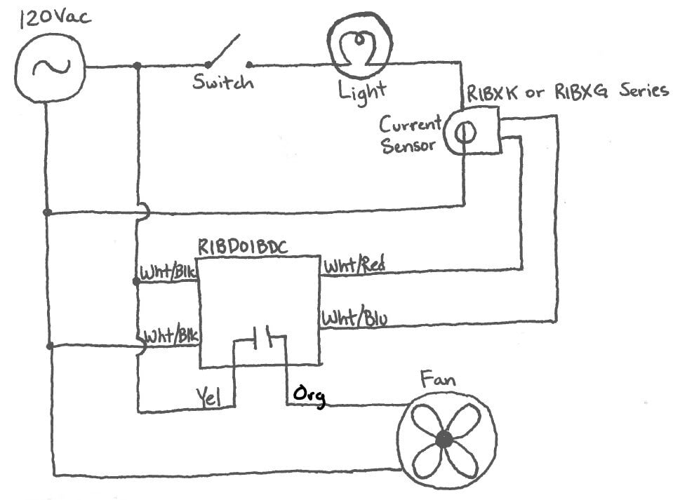
Solution: Use a RIB® Current Sensor and Delay on Break (DOB) Time Delay Relay per the diagram below:

How does this work?
When the switch is open in the diagram above, the light is OFF. With the light drawing no current through the sensor, the sensor output will be open. With power applied to the RIBD01BDC and the dry contact input (Wht/Red and Wht/Blu) open, the Normally Open (NO) relay contact in the RIBD01BDC will be open. This means the bathroom exhaust fan will also be OFF.
When the switch is closed, the light will turn ON. That will draw current through the sensor, causing its output to close. As soon as the RIBD01BDC sees the contact closure on its input, the NO contact will close again. At this stage, the bathroom exhaust fan will be powered.
When the switch is opened, the light turns OFF and draws no current. This will cause the current sensor output to open. This in turn opens the input on the time delay RIB® and initiates its timing. Once the settable time delay period ends, the NO contact of the relay will open again, and the fan will turn OFF.
While the diagram above shows a 120 Vac circuit, the same can be accomplished on a higher voltage (208-277 Vac) circuit by using model RIBD02BDC. A key factor in getting this setup to work is ensuring that the current drawn by the lighting load is above the threshold of the current sensor being used.
If you have any questions, please feel free to contact our Support Engineers M-F 8am-5pm EST.
