There’s a reason for the saying, “Don’t get your wires crossed.” When it comes to electrical wiring, safety is paramount. Fortunately, Functional Devices relay wiring is pretty straightforward. Read on for the essential details in our RIB® relay wiring guide to help make RIB relay installation go more smoothly, efficiently, and of course… safely!
Functional Devices has been making electrical components for a long time. Over 50 years, in fact! If you ever have any questions about safe installation, don’t hesitate to reach out to our tech team. We can walk you through the RIB relay installation for your specific model and application.
Safety Disclaimer: This procedure assumes the installer has working knowledge of electrical circuits, control wiring, and applicable electrical codes (NEC/CEC). Always de-energize circuits at the disconnect or breaker, verify zero voltage using a true-RMS multimeter, and follow all OSHA and NFPA 70E safety guidelines. Improper wiring can cause equipment failure, fire hazards, or personal injury.
What Is a RIB?
RIB (Relay-In-a-Box) relays come as enclosed electromechanical relays with pre-wired leads. They offer many advantages, including reduced installation time, simplified wiring, multiple mounting options, and pre-spliced pigtails. You’ll spy them used in a variety of applications like interfacing low-voltage control circuits with high-voltage loads, load isolation, current sensing, time delay control, and more.

That all sounds nice, but how to wire a RIB relay remains the question. With such a list of accolades, surely they’d be complicated to install, right? Nope! Because they come preassembled, wiring (dare we say it) becomes easy. Let’s dive into wiring a RIB relay step-by-step and ease any of your fears.
Step 1: Verify System Specifications and Select Correct Relay
Before you go to the trouble of disconnecting power or installing, make sure you have the right relay for the job. Verify by:
- Confirming the coil voltage rating (e.g., 24 VAC, 120 VAC, 208–277 VAC)
- Determine contact configuration (SPDT vs. DPDT) and contact rating (e.g., 10A FLA, 20A resistive, pilot duty)
- Reviewing form factor of the relay (e.g., enclosed, track mount, DIN mount, weather tight)
When in doubt, reach out to us. It’s easier to verify first than to have to stop your project mid-install when you discover you have the wrong model.
Step 2: Gather Tools, Test Equipment, and Materials
Next, prepare the stage. Gather necessary tools, like insulated screwdrivers, torque driver, wire strippers (AWG 18–10 range), and long-nose pliers, and materials, including appropriate gauge wire per NEC 310.16, UL-listed wire connectors, cable ties, and labeling tags.
Use a true-RMS multimeter, non-contact voltage tester, and continuity tester to confirm the relay’s:
- Contact continuity (de-energized and energized)
- Switching action
- Voltage
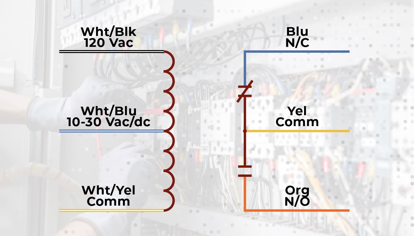
Step 3: Interpret the Relay Wiring Diagram
Look at the relay wiring diagram before installation. Here’s what to identify:
- Coil terminals/leads
- COM (common), NO (normally open), and NC (normally closed) contact leads
- Wiring topology
Step 4: Lockout/Tagout (LOTO) and Verify De-Energization
Now it’s time for the most important step: ensuring your safety by physically locking energy isolating devices, like circuit breakers.
- Open the disconnect switch or breaker feeding both control and load circuits
- Apply lockout/tagout device with clear identification
- Verify with multimeter from each lead to ground and between leads (should read 0 VAC)
Following proper LOTO procedure ensures others can’t accidentally restart or re-energize equipment.
Step 5: Mount the Relay Enclosure
In order to move somewhere new, you need a house to move into. That’s what an enclosure is for a relay, and fortunately for you, the RIB relay comes already “moved into” its house. Functional Devices offers several different mounting options, including:
- Surface screw mount
- Snap track
- DIN rail
If necessary, ensure mounting location meets NEMA enclosure requirements for the environment, like NEMA 4/4X options for outdoor protection.
When mounting the enclosure, route wires to avoid sharp bends and mechanical stress.
Step 6: Wire the Coil Circuit
Now the time you’ve all been waiting for… the part with wires! First up, the coil circuit (aka the wires that send a signal to the relay). First, follow the datasheet to connect control signal wires to coil leads using UL-listed connectors. Then torque to the model’s specs.
Using your multimeter, observe that the polarity is correct for DC coils (if applicable; polarity not required for AC coils). For multi-voltage relays, insulate unused coil leads per manufacturer instructions.

Step 7: Wire the Load Circuit
You’ve got a signal now coming into the relay coil, and now you need to switch power on the contact side of the relay for the load that is to be controlled.
Remember to terminate:
- COM (common) to line or load feed per application
- NO (normally open) or NC (normally closed) to load as required by control logic
Ensure contact ampacity matches load inrush and running current according to the datasheet. You may need to derate for inductive or capacitive loads, thus limiting the applied voltage below the rated voltage.
Step 8: Secure and Organize Wiring
Once the coil and load circuits are wired, it’s time for some finishing touches. First, secure and organize wiring by applying cable ties and strain relief to prevent movement. Second, consider placement: route control and line-voltage wiring separately when possible to reduce electrical noise.
Additionally, verify conductor insulation is not nicked or damaged so that your wiring is properly protected and safe.
Step 9: Functional Testing
Before signing off on an install, you need to test that the relay is working properly. To do that, you have to remove LOTO and re-energize the circuit.
Important Safety Note: Before re-energizing, ensure all tools are removed, PPE is worn, and no personnel are in contact with components. Then carefully remove LOTO and re-energize the circuit.
Then, apply a control signal and verify that the relay coil energizes (audible click, LED indicator if present). Test to see if the load energizes and de-energizes per intended sequence. Using your multimeter, measure coil draw and contact voltage to confirm within specifications.
Step 10: Final Inspection and Documentation
Almost time to party… but not quite yet. Close and secure the enclosure cover, give everything a final visual inspection, and keep necessary documentation for maintenance records, such as:
- Record relay model
- Wiring configuration
- Installation date
- Data sheet
Additionally, physically label the control panel or relay enclosure for even quicker identification.

Still Have Questions About RIB Relay Installation?
Congratulations, now it’s party time. You’ve successfully navigated how to wire a RIB relay! Choosing the correct relay, precise wiring, and compliance with codes ensure system reliability.
For maintenance, we recommend periodic inspections for contact wear, coil degradation, and secure terminations. For a more comprehensive maintenance plan, check out our maintenance checklist.
As always, if you have any questions please feel free to contact our team. We’d be happy to help guide you through an RIB relay installation more catered to your application.