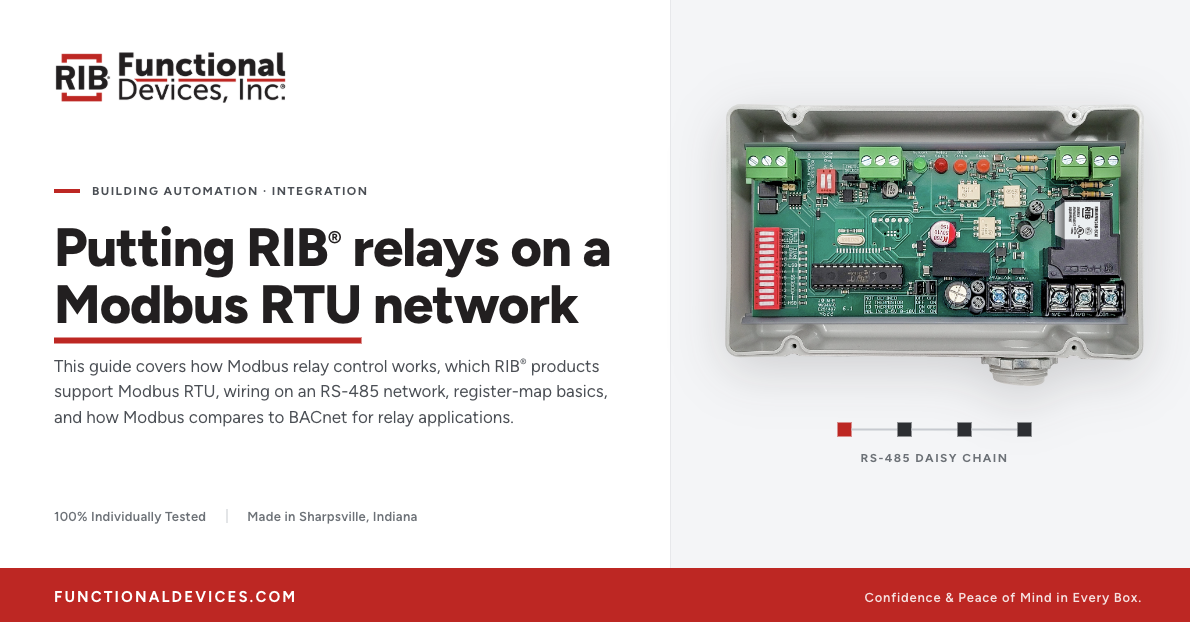
A Modbus relay lets a controller switch a physical load over a Modbus RTU network: the master writes to a coil or register, and the relay closes its contacts to energize a fan, pump, valve, or lighting circuit. The network carries the command; the relay does the switching.
Functional Devices, Inc. manufactures RIB® (Relay-In-a-Box®) relays, current sensors, and power supplies for building automation system (BAS) work—including an enclosed relay that operates as an addressable device on a Modbus RTU network, and standard relays driven by a Modbus controller's output. This guide covers how Modbus relay control works, which RIB® products support Modbus RTU, wiring on an RS-485 network, register-map basics, and how Modbus compares to BACnet for relay applications.

What Is Modbus RTU?
Modbus is a serial communication protocol. Modbus RTU is the binary variant that runs over an RS-485 (or RS-232) serial line, and it is the most common form in the field. It uses a master/slave structure: one master polls one or more slave devices, and each slave has a unique address in the range 1–247. The bus is half-duplex, so only one device transmits at a time, and a single RS-485 segment supports up to 32 devices before repeaters are needed.
Modbus organizes data into four types: coils (single-bit, read/write outputs), discrete inputs (single-bit, read-only), input registers (16-bit, read-only), and holding registers (16-bit, read/write). The master reaches them with function codes — read coils, write single coil, read holding or input registers, write single register, and so on.
One point shapes everything downstream: Modbus standardizes how to access data, but not what the data means. A register holds a value; whether that value is a relay state, a temperature, or a baud-rate setting is defined by the device manufacturer and documented in the device's register map. That is different from an object-oriented protocol like BACnet, and it is why the register map matters for every Modbus device.
How Modbus Relay Control Works
A relay fits a Modbus system in one of two ways.
The first is a standard relay driven by a controller output. A Modbus controller or I/O module receives a command over the network, sets a physical output, and that output drives the relay coil. The relay is not on the Modbus network at all. RIB® relays are protocol-agnostic at the hardware level: the coil responds to voltage, not to network commands. The same relay works behind a Modbus controller, a BACnet controller, or a thermostat.
The second is a network relay that is itself a Modbus slave on the RS-485 bus. The master writes to a coil or register at the relay's address to switch its contacts and reads back status; on a model with an analog input, the master also reads the sensed value. No separate controller output is required, which can remove a point from a larger controller for a simple add-on.
In both cases the relay is the point where a digital command becomes a physical action, and it provides electrical isolation between the controller or network and line voltage.

RIB® Relays with Modbus RTU Support
For network-native Modbus, the RIBTW24B-MBAI is an enclosed Modbus RTU relay with separated high/low 20A switching, a 24 VAC/DC supply, and an analog input. It operates as an addressable device on the RS-485 bus; the "-MB" suffix marks the Modbus version, paralleling the "-BC" BACnet line. See the current list of models offered by Functional Devices in the RIB® relay catalog.
Where a Modbus controller or I/O module already provides the output, any standard RIB® relay serves as the switching device. The RIBU1C (10A SPDT, universal 10–30 VAC/DC or 120 VAC coil) covers light-duty and pilot-duty points; the RIB2401B (20A SPDT, 24 VAC/DC or 120 VAC coil) covers most fan and rooftop switching; the RIB24P30 (30A DPDT, 24 VAC/DC coil) covers higher-current or dual-circuit loads. Match the coil voltage to the controller output and check the contact rating against the load.
Wiring a Modbus Relay in a BAS Network
A Modbus RTU network is an RS-485 bus wired in a daisy chain, two data conductors plus a common reference. Observe A/B polarity, terminate the two ends of the trunk, and give each device a unique slave address with a matching baud rate and parity.
For a network relay such as the RIBTW24B-MBAI: land it on the RS-485 trunk, assign its Modbus address and serial settings, supply 24 VAC/DC, and wire the load to the contacts. For a standard relay, the Modbus device is the controller or I/O module. Its output drives the relay coil, and the relay switches the load, the same controller-to-relay chain used in any BAS. Either way, the enclosed, UL Listed relay isolates the control side from line voltage. Confirm the RS-485 settings—address, baud rate, parity, and termination—against the device datasheet before commissioning.
Register Map Overview
Because Modbus does not define what a value means, a Modbus device ships with a register map: the document that lists which coil and register addresses control and report what. For a Modbus relay, the map identifies the coil or holding register that commands the relay state, the discrete input or register that reports status, the holding registers that hold configuration such as slave address and baud rate, and, on a model with an analog input, the input register that holds the sensed value.
The function codes are the standard set: read coils and write single coil to operate the relay, read holding or input registers to retrieve values, write single register to change a setting. The addresses themselves are model-specific. Take them from the Modbus register map for the exact Functional Devices model in use, available with the product documentation; do not carry addresses over from another device or vendor.

Modbus vs. BACnet for Relay Applications
Modbus RTU and BACnet MS/TP both run on an RS-485 serial bus at the field level, but they differ in structure. Modbus RTU uses master/slave polling and a flat register model; BACnet MS/TP uses token-passing and an object-oriented model.
Modbus is simpler, has lower overhead, and is straightforward to troubleshoot, which is why it is common on meters, drives, and equipment with modest point counts; its tradeoff is that register meaning is vendor-defined, so integration depends on careful register mapping. BACnet is an ASHRAE/ISO open standard built for building automation, with defined objects for HVAC data and stronger cross-vendor interoperability, at the cost of more configuration.
For relay control, the switching function is identical. The difference is how the relay is addressed and how its status is reported. On a Modbus network, use a Modbus network relay or a standard relay on a Modbus I/O point. On a BACnet network, Functional Devices offers BACnet network relays such as the RIBTW2401B-BC; see the guide to RIB® relays and BACnet controller integration and using BACnet-compatible RIB® relays. Where the two protocols meet, a Modbus-to-BACnet gateway bridges them.
Frequently Asked Questions
What is a Modbus relay?
A relay controlled over a Modbus network. It is either a relay that is itself an addressable Modbus slave, or a standard relay switched by the output of a Modbus controller.
Can a RIB® relay work on a Modbus RTU network?
Yes. The RIBTW24B-MBAI operates as an addressable Modbus RTU device on the RS-485 bus. Standard RIB® relays work as the switching device on a Modbus controller's output. Match the coil voltage to the controller output and confirm the RS-485 settings against the datasheet.
Where do I find the register addresses for a Modbus relay?
In the device's Modbus register map, supplied with the product documentation. Because Modbus does not standardize what a value means, use the register map for the exact model rather than assuming addresses from another device.
Is Modbus or BACnet better for relay control?
The switching function is the same; the choice usually follows the host system. A Modbus network calls for a Modbus relay or a relay on a Modbus I/O point; a BACnet network calls for a BACnet relay or a relay on a BACnet output.

Specifying a Modbus Relay
On a Modbus network, the relay is where a register write becomes a switched load. Use a Modbus network relay where the relay should sit on the RS-485 bus and report its own status, or a standard RIB® relay where a Modbus controller output drives it. Match coil voltage and contact rating to the application, take register addresses from the model's own register map, and confirm RS-485 settings on the datasheet.
To select a relay, see the RIBTW24B-MBAI product page, browse the RIB® relay lineup, or find an authorized Functional Devices distributor.