A current sensor confirms whether a load in a machine is actually running, and determining the correct model depends on the amount of current the load draws and the intended use of the sensor’s output. An equipment builder specifying sensing and switching into a machine or control panel is often choosing between devices that look similar on a shelf but behave very differently once they’re wired to a load.
Functional Devices, Inc. manufactures current sensors and relays for building automation and equipment integration, including split-core switches with adjustable thresholds and models built for the low standby currents of electronically commutated motors. This guide covers how to match a current sensor to the load it monitors, where the common selection mistakes happen, and how relays pair with it.

How a Current Sensor Reports Status
A current sensor determines whether or not the monitored conductor is carrying current above a set threshold. When a load runs, the sensor’s contact changes state and reports that status to a controller. The reason to sense current rather than command state is that a commanded output can be on while the load itself has failed—a seized motor, a broken belt, or a blown fuse, for example—and only a reading taken at the conductor can fully determine the difference.
Most current sensors used for equipment status are split-core devices. This means that the core opens so the sensor clamps around an existing conductor without needing the circuit to be broken. Current in the conductor induces a signal in the sensor. Then, above a set threshold, the sensor closes a dry contact that a controller reads as an on/off status point.
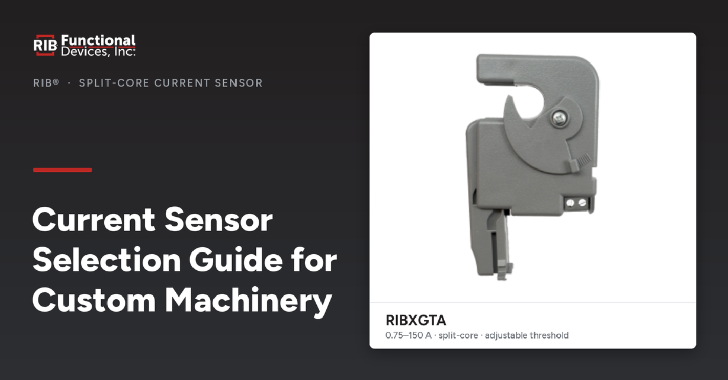
The RIBXGTA is a representative model for this use. It’s an enclosed split-core AC sensor with a sensing range of 0.75–150 A and an adjustable threshold, terminating to a screw terminal strip. It closes a dry contact when monitored current crosses a set threshold, which is the output a building automation system or machine controller typically expects for a status input. Because this same sensor often has to serve loads of very different sizes, the threshold is adjustable; the installer sets the trip point to sit between the load’s off state and its running draw.
Output type also governs selection. A dry-contact closure is passive; it carries no power of its own and simply opens or closes for the controller to sense. That is the correct output for a status point. A sensor with a different output, such as an analog signal proportional to current, serves a different purpose (trend logging, load analysis) and is not interchangeable with a switch, even if the sensing range overlaps.
Matching the Sensor to the Load
Standard Loads
For loads that draw a clear running current well above zero, such as a conventional fan, pump, or three-phase motor, a split-core switch like the RIBXGTA is often the appropriate choice. Its running draw is several amps higher than its off state, so the threshold has a large enough margin that a false reading is unlikely.
Low-Current and ECM Loads
Electronically commutated motors are more complicated. An ECM has an onboard control board that always draws a small standby current, so the trip point cannot be set to zero, and the running current can also be low and variable. This means that a standard switch may not distinguish standby from running.
The RIBXGTA-ECM is built for this use case. It has an adjustable threshold down to 0.25 A (sensing range 0.25–150 A) with a tight hysteresis band, so it can differentiate a running ECM from its standby draw. It also has LED indicators that guide the installer in setting the trip point at the true operating current rather than the standby level.
Self-Calibrating Installs
For installations where setting a threshold by hand is impractical, the RIBXGTA-SCAL is a self-calibrating split-core sensor (3–150 A) that establishes its own trip point, removing the manual adjustment step entirely.

A Common Selection Mistake
Contact behavior is a very important selection criterion. The RIBXGTA and the RIBXGTA-SCAL, for example, share a 0.75–150 A range and both are split-core, but their contacts behave differently. The RIBXGTA has a dry-contact closure, whereas the RIBXGHTA does not behave the same way as a plain dry-contact output, so specifying it for a status input on the assumption that matching ranges mean matching function produces a device that will not report status as expected.
Pairing a Sensor with a Switching Relay
In a machine or panel, a current sensor and relay are typically specified together. The relay should be selected to suit the load it switches and the coil signal available to drive it.
The RIBU1C is a general-purpose enclosed relay with a 10–30 Vac/dc or 120 Vac coil and 10 A SPDT contacts, providing a dry, isolated contact output. It is well suited to switching low-to-medium loads from a control signal, including the low-current and digital signals its gold-flash contacts support. It is not rated for electronic ballast switching.
For heavier loads, the RIB2401B provides 20 A SPDT contacts with a 24 Vac/dc or 120 Vac coil in a NEMA 1 enclosure, and the RIB2402B carries the same 20 A rating for 208–277 Vac equipment.
Where one signal has to switch two circuits—reversing a motor, controlling dual loads—the RIB24P provides 20 A DPDT contacts from a 24 Vac/dc coil. For logic driven by a contact rather than an applied coil voltage, the RIB01BDC takes a dry-contact trigger, which suits sensor- or switch-driven control.
When a single device has to sense current and switch a load at the same point, the RIBXLCRA—which combines a current sensor and relay in the same enclosure—is a great choice.

Frequently Asked Questions About Current Sensor Selection
What does a current sensor do in a machine?
It confirms whether a monitored load is actually drawing current, and reports that as a status point to a controller. Because a commanded output can be “on” even if the load has failed, a reading taken at the conductor is a much more reliable indicator that a load is really running.
How do I set the threshold on an adjustable current sensor?
The threshold should be set to sit between the load’s off state and its running current, so the contact changes state only when the load runs. On low-current loads such as ECMs, the trip point must clear the standby draw. A sensor with LED indicators, like the RIBXGTA-ECM, can guide an installer in determining that threshold.
Why won’t a standard current switch work on an ECM?
An ECM’s control board draws a standby current at all times and its running current can be low and variable, so a standard switch may not be able to separate running draw from standby draw. A sensor built for low-current detection with tight hysteresis, such as the RIBXGTA-ECM, resolves that difference down to 0.25 A.
Do I need a separate relay if I have a current sensor?
A current sensor reports status; it does not switch a load. If the same point has to both sense and switch, the RIBXLCRA combines sensing and a relay in one enclosure. Otherwise the sensor and a switching relay are specified as two devices.

Specify the Right Current Sensor for Your Build
To specify sensing and switching for a build, browse the Functional Devices current sensor and relay lineups, or contact Functional Devices for assistance with matching the correct device to your build.